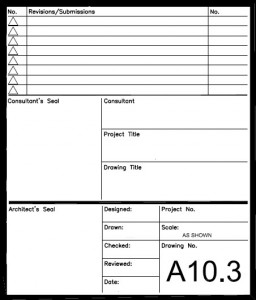
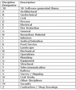
When you are writing your CAD Standard you should consider including a lengthy explanation of your Border and Title Block file. Take the time to make sure that everyone knows where the correct files are and what goes where. Don’t let the project team get creative on the location of standard information. Don’t let them just copy the border from the last project they worked on.
Show example screen shots of each area of the border and define what goes where.
Showing users exactly what they expect to see when a Title Block is added and filled in will help tremendously. Don’t leave it to them to guess. Make notations as to what each area of the Title Block is supposed to contain and convey.
Include exact fonts and sizes for all text that the users may be placing.
Example text that could be included in your standard:
When referenced, the insert point for the titleblock/border file is 0,0,0 in Paper Space.
A titleblock attribute text block will be provided. Included in this block will be the typical symbol blocks and text styles required to annotate the plot/sheet file.
Titleblock entities will be placed the G-ANNO-TTLB layers. Typical layers for the titleblock will be G-TTLB, G-TTLB-ANNO, G-TTLB-KPLN & G-TTLB-GRID.
The key plan will be located in a space above the Issue Block area. Place the key plan on layer G-TTLB-KPLN.
Matchlines will be placed in Paper Space. It may be necessary to also place matchlines in model files, so other disciplines can find the matchlines.
North arrow and scale(s) will placed in the lower right hand area of the drawing area, just left of the Sheet number.
The Border File is one that is used on every sheet file and every project you have. Getting it right shows that you really have your act together. Getting it wrong can tell others that your level of quality is slipping. I have been in meetings and have seen the clients name spelled wrong on the border and have it show up on every sheet. I have seen mistakes in peoples name, titles, locations, addresses, project numbers and more.
Project Managers and those that interact with the client take the brunt of these discussions. They are in the meetings with the clients and owners. If the client is the one that catches these mistakes – it makes them look pretty bad. You don’t want to have that happen very often. They can come back from meetings with a very sour attitude.
Reviewing Your Border
Take the time needed to fully define and refine your border files. If you have a standard company border that is used on every project, then get it perfect. Review the look and feel issues fist. Does it have all the info needed? Does it reflect the current locations of your firms offices? Does it look like it was created in 1950? Is it time to change the look? Does it reflect the current format of other collateral that your firm uses like letterhead layout, logos, fonts, etc.?
Now that the look is defined then take a long look at the layers you are using. Keep them as simple as you can. Reduce the layers that you use to the most minimal that get the job done. Use color to your advantage. If you are using CTB for plotting then don’t let the layer colors stray from something simple. If you are using STB, then make the colors pleasing on the eye.
Reduce the fonts and linetypes used. Does it use non-AutoCAD standard fonts? Are you using TrueType fonts that may not reproduce on other folks plotters and screens? Consider using PLINE for thickness and not color. Consider gapping CONTINUOUS lines in place of linestyles which can be impacted by someone changing LTSCALE.
Is the Logo an Image? Most CAD packages are handling images better, but I would still consider redrawing your company logo in CAD and not using an image file. The image files are usually externally referenced into the files and can be left behind when transmitting the deliverables.
Cleaning up the File
Now that you have reviewed and perfected the look and layers – Clean the file up. Leaving artifacts from unused data clutters the file up. Take an extended time period to get all the junk out of the file. PURGE the file to death. WBLOCK it out to another file. Check REGAPPS. Check residual fonts, layers and more. Check it, Check it, Check it. Clean it, Clean it, Clean it.
Once it is clean (you did clean it – right?) put it into a central location and lock it down. Do not let users fiddle with the standard file. They may copy it into their project location, but they should not adjust any of the standard border graphics or data.
AUGI and Extension Media are excited to announce AUGI AEC Edge – A new publication launched today that is focused on the AEC industry.
AUGI AEC Edge is dedicated to providing cutting edge industry information and useful tips on all aspects of Autodesk’s digital design software necessary for accurate project design, visualization and analysis. This valuable information will enable readers to deliver their projects faster, with greater accuracy, creativity and with reduced environmental impact.
The Premiere issue of AUGI AEC Edge will focus on exciting developments in the Building Information Modeling (BIM) process and Revit solutions with features articles, news, and contributions from industry leaders. Editorial leadership for this innovative publication is provided by AUGI.
Read More… on BLAUGI
Image Files
20 characters maximum (not including filetype extension).
Common image file extensions will be .TIF, .JPG and .BMP. Image files are placed into the Sheet folder and referenced only to Sheet files. They may also be referenced to Model files as needed.
Standard: ZPPAD-**************
Z: Identified the file as an Image file to be Attached to other files.
PP-: Project identifier (2 characters) (Optional)
A: Phase identifier (Optional) (1 character or “-“ (hyphen))
D-: Discipline (1 character)
*****: File description (14 characters)
Examples:
ZSC-A-KEYPLAN.JPG
ZA-DOOR102.TIF
ZA-SLABJOINT.BMP
ZG-LOBBY-NORTH.JPG
File Description Options:
o bldg identifier/number
o interior
o exterior
o equipment type
o location of picture
o direction of view
This is an opportunity for some free online training…
Here is the information they provided to me…
Venue/Location: Live and OnDemand Formats
Date: Starting June 23, 2009 through November 30, 2009
Register Now by visiting www.bentley.com/BeConnected
Bentley Systems’ Be Connected online seminar series gives architects, engineers, builders, geospatial professionals, and owner-operators a chance to learn about applying information modelling from some of the world’s leading infrastructure practitioners.
The conference series begins on June 23, is free of charge, in both live and OnDemand formats, and takes the place of this year’s Be Conference.
Be Connected offers two types of online seminars:
1) Best Practices Seminars. Presented by leading infrastructure professionals around the globe, these sessions bring a project perspective on best practices for the design, construction, and operation of specific types of infrastructure projects, including a series of seminars on each of the following: bridges, cadastre and land development, communications, electric and gas utilities, high performance buildings, mining and metals, oil and gas, rail and transit, roads, and water and wastewater.
2) Product Seminars. Presented by Bentley’s product executives and designed for both current and prospective users, these technology-focused sessions demonstrate the latest features and capabilities of Bentley’s comprehensive V8i software portfolio for sustaining infrastructure.
Sheet Files
14 characters maximum (not including file type extension)
Standard: PPAD-TT-LLL_R
PP: Project Identifier (2 characters) (Optional)
A: Phase Identifier (1 character or “-“) (optional)
D: Discipline (1 character)
“-“: hyphen
TT: File Type (2 character) (Optional)
LLL: Sheet Number (3 characters )
_R: Revision suffix – (Optional 1 character and placeholder as required)
Examples:
PC-A-FP210.dwg = Pima County, Architectural, Floor Plan, Sheet 2.10
S8AC-PR615.dwg = Santana segment 8, Phase A, Civil, Profile, Sheet 6.15
A-201.dwg – Arch Sheet 201 with no optional characters
XREF (Background) Files
9 characters maximum (not including filetype extension)
Standard: XPPA-DTTLL
X PP A(-) D TT LL
X: Identified the file as a Model file to be XREFed to other files.
PP-: Project identifier (2 characters) (Optional)
A: Phase identifier (Optional) (1 character or “-“ (hyphen))
D: Discipline (1 character)
TT: File type (2 character)
LL: Floor/series identifier (2 character)
Examples:
XPC-AFP01.dwg
Pima County, Architectural, Floor Plan, First floor
XPC-CSP01.dwg
Pima County, Civil, Site Plan, #1
XS8ACSP01.dwg
Segment 8, Phase A, Civil, Site Plan, Mainline (#1)
XAFP01.dwg = Arch Floor Plan, First Floor (No Optional characters)
Every Standard has to have a way to identify what file type you have. Having a designator in the file name can help everyone know who is overseeing what.
Here is an example – again – it is NCS compliant.
File Type Designator examples:
ARCHITECTURAL & INTERIORS:
AD Area Development
DP Demolition Plan
EL Elevation
EP Equipment Plan
FE Fire Egress Plan
FI Finish And Material Plan
FM Mezzanine Floor Plan
FP Floor Plan
FU Furniture Plan
GR Grid Layout
LP Landscape And Paving Plan
MP Master Layout Plan
RC Reflected Ceiling Plan
RP Roof Plan
SC Section
SH Schedules
SP Site Plan
SS Specialty Systems
VC Vertical Circulation Plan
WS Wall Section
XE Enlarged Elevation
XL Enlarged Floor Plan
XP Existing Plan
XR Existing Reflected Ceiling Plan
XS Enlarged Section


