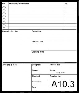
When you are writing your CAD Standard you should consider including a lengthy explanation of your Border and Title Block file. Take the time to make sure that everyone knows where the correct files are and what goes where. Don’t let the project team get creative on the location of standard information. Don’t let them just copy the border from the last project they worked on.
Show example screen shots of each area of the border and define what goes where.
Showing users exactly what they expect to see when a Title Block is added and filled in will help tremendously. Don’t leave it to them to guess. Make notations as to what each area of the Title Block is supposed to contain and convey.
Include exact fonts and sizes for all text that the users may be placing.
Example text that could be included in your standard:
When referenced, the insert point for the titleblock/border file is 0,0,0 in Paper Space.
A titleblock attribute text block will be provided. Included in this block will be the typical symbol blocks and text styles required to annotate the plot/sheet file.
Titleblock entities will be placed the G-ANNO-TTLB layers. Typical layers for the titleblock will be G-TTLB, G-TTLB-ANNO, G-TTLB-KPLN & G-TTLB-GRID.
The key plan will be located in a space above the Issue Block area. Place the key plan on layer G-TTLB-KPLN.
Matchlines will be placed in Paper Space. It may be necessary to also place matchlines in model files, so other disciplines can find the matchlines.
North arrow and scale(s) will placed in the lower right hand area of the drawing area, just left of the Sheet number.
