Personal CAD Standards impact everyone because they are not shared. Each person is doing what they want. This causes files to differ from one person to another. These differences cause production slow downs.
Outdated CAD Standards can do the same thing. Here are a few things that might happen if your CAD Standard is out of date:
1. You don’t use the power of the newest tools. You are stuck complying with a standard that was created 2 or 3 releases back. Missing out on the productivity can be harmful.
2. You have trouble interacting with others. You get files from other firms that use newer features and you have to “dumb them down” so that you can work on them.
3. You force guidelines on people that are no longer valid. Cramping the expansion of your team based on guidelines that do not take into account the changes in the industry.
4. You get a false sense of productivity. You may be faster doing CAD in an older fashion but no one else is.
5. You do not include newer methods of organization that might be available. Not just the tools have advanced, but your users have also. They have found new ways of doing things, but you have not included them in the standard. This fails to share the latest processes with the entire team.
6. You set your standard up for being ignored. People will soon stop using it.
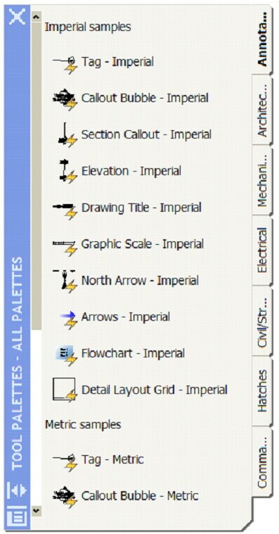
Here is an example of the way you might document the symbols in your Standard
You may say – “They are in my menus and in my folders. Everyone knows what they look like.”
The reason I suggest that you add graphic examples is so that no one will be confused. New users may not know what is expected. Those using symbols from old projects may not know they are incorrect.
Show them what they symbols should look like.
When you create your CAD Standard you have to define the symbols that are to be used.
Questions for your CAD Standard…
- Are your symbols documented?
- Will you provide symbols to other firms that are working on your projects?
- Are they created correctly? – sounds funny, but there are a lot of symbols that have not been created perfectly.
- Do you have a menu or tool palette that incorporates the symbols?
- Will you use “out of the box” symbols if you use advanced software?
- Do your symbols mimic the National CAD Standard symbology?
Include graphics of your symbols in your Appendix. This includes the General Drafting Symbols and the Discipline symbols.
Include an outline of the size, fonts, etc. related to the symbols.
Define the layer to be used – “The standard symbols are to be inserted on layer G-ANNO-SYMB.”
Define what happens if a symbol does not exist… “If there is no symbol for the item you need – you may use an industry or office standard symbol.”
Revisions are what CAD is all about. Back in the day of hand drafting, people had to use erasers and redraw everything even if it move an eighth of an inch. There were fancy erasing machines and erasing shields.
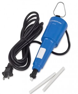
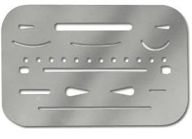
Now that CAD allows you to change your mind and adjust drawings so quickly – we do it a lot.
Managing CAD Revisions is part of the editing process. Most firms have some fashion of tracking revisions to drawings and it does need to be managed in CAD also.
Here are some options that you could include in your standard related to revisions.
Clouds will be drawn to encompass the area of the revised work. The clouds shall be drawn with the annotation tools provided in AutoCAD.
Each revision will be identified by means of a revision triangle or delta and a number identifying the revisions in consecutive manner. The revision symbol shall be placed touching the cloud, inside the cloud or next to the cloud and connected to it by means of a small leader or arc.
All revision symbols and clouds shall be drawn in Paper Space in the sheet (plotting) file. No revision symbols or clouds shall be drawn in the Model files.
Each revision cloud will be drawn in its corresponding layer. The layer name shall include the number of the revision. There shall be as many such layer names as revisions issued. The layer name for the cloud shall be G-ANNO-REVC-REV#, where # stands for the corresponding revision number as listed in the Issue Block.
Each revision symbol will be drawn in its corresponding layer. Place all deltas on the same layer. The layer name for the revision symbol shall be G-ANNO-REVS.
As revisions are superseded, the old revision cloud layers shall be Frozen. All revision symbols shall remain visible as a permanent historical record of revised work in the sheet.
In cases where the revision clouds must be preserved due to specific project or authority requirements, the clouds of superseded forced to a screened color.
The revision note that is placed in the Title Block Revision area shall be drawn in a separate layer. The layer name for the revision symbol shall be G-ANNO-TTLB. All revision notes in the Title Block shall be drawn in this layer.
The format for the revision note shall be a revision symbol with the number of the revision, a numerical date of issue and a brief descriptive note of the revised work.
I have been so busy getting my handouts and presentations done for AU 2009 that I just have not had time to post on my blog…
Here is a sneak peek from my two classes…
CADD Leadership 2009
What got you here – won’t get you there
- When you started down this road you had no CAD Skills
- Once you got CAD Skills you thought… Maybe I could be a CAD Manager…
- So you added Management Skills
- Then you thought… Why am I still having trouble…
- You need to add Leadership Skills!
Leading from your Strength…
Gallup Poll on what the boss wants to see…
- Resourcefulness (81 percent)
- Decisiveness (75 percent)
- Managing change (69 percent)
- Straightforwardness and composure (68 percent)
- Building and mending relationships (67 percent)
- Doing whatever it takes (67 percent)
- Employing a participative management style (64 percent)
BIM Manager – the Newest Position
The Changes of BIM
BIM requires you to…
- forget old habits
- reinvent old work flow
- redefine project teams
- refine design team coordination processes
- establishing levels of design detail in BIM
- investigate changes to billing and invoicing your clients
- investigate changes to design support functionality (specs and estimating)
- rethink accounting, billing, PM workflow
Just found this “surfin the web”…
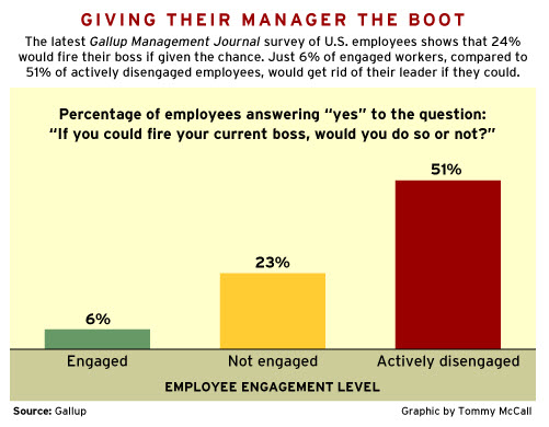
Nearly one-quarter of U.S. employees (24%) would fire their boss if given the chance. And as many as 51% of actively disengaged workers would get rid of their leader if they could.
These findings were gleaned from a Gallup Management Journal ( GMJ) survey of U.S. employees. Gallup researchers studied employee responses to see which factors differed most strongly among engaged employees (26% of respondents) and those who were not engaged (56%) or actively disengaged (18%).
On the personal side… I would not fire my boss.
You can add some very basic AutoCAD information to Windows Explorer that might help you as you try to keep track of what is going on in your firm or project.
Have you ever wondered what version of AutoCAD the file was created in? Have you ever opened a file that was a newer version than what you have only to get the stark warning alert that it will not work?
Well this might be just what you need.
You can add DWG Creation software Name and Version in a Windows Explorer column.
Step one:
Right click on the column heading in a Windows Explorer session.
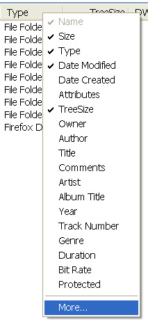
You will get a drop down check box like above – Select More… this will open a Dialog Box…
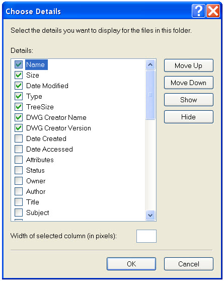
Check the DWG Creator Name and the DWG Creator Version options… You may have to scroll down to find the. They may be lower on you screen than what is shown above.
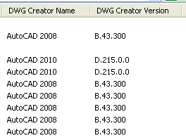
Once selected and saved you will see the above columns added to your Explorer window. These columns will show the version that the file was last saved in and ver version number (not sure where this might come in handy)
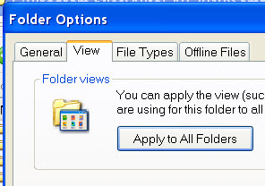
If you want tohave all your Explorer views to match what you see, select Folder Options and the View Tab and click on Apply to All Folders.
The shout goes up… Save it or Lose it!
That was the reminder that we all used say to keep our files safe. We were addressing the fact that a computer crash may take out your work. If it was not saved back to the server, then it might be lost. Sometimes this would be said in frustration by one that had just been bitten by a crash (software or hardware). Sometimes it was just a casual reminder.
You may not be needing reminders like this to make sure that your users are remembering to save, but you do need to think about the whole save process.
How often do you save?
Do you rely on AutoSaves to save your files?
Do they even think about saving?
How much data are you willing to risk in an unsaved file?
AutoSaves are not real saves of your file data. It is a save to local. The location is defined by the SAVEFILEPATH variable.
SAVETIME
This is the system variable that sets the automatic save interval, in minutes.
0 – Turns off automatic saving.
>0 – Saves the drawing at intervals specified by the nonzero integer automatically
The value of SAVETIME is an integer between 0 and 600 minutes.
The SAVETIME timer starts as soon as you make a change to a drawing. It is reset and restarted by a manual QSAVE, SAVE, or SAVEAS.
So what do you set your Save Time as ?
I think that if you are in a good habit of saving your files and are not forgetful, then set it higher than 10 minutes. You could even turn it off (not recommended). If you are not in the habit of saving then set it lower or at 10 minutes.
My other Save rule of thumb… save you drawing every 10-15 minutes or so and after every major operation. Also save it when you are interrupted, leave your desk or get a phone call or chat message that might derail your thought process.
You can set the time of an AutoSave in the Options Dialog box.

Automatic Save
Saves your drawing automatically at the intervals you specify. You can specify the location of all Autosave files by using the SAVEFILEPATH system variable. SAVEFILE (read-only) stores the name of the Autosave file.
Note: Automatic save is disabled when the Block Editor is open.
Minutes Between Saves: When Automatic Save is on, specifies how often the drawing is saved. (SAVETIME system variable)
System Variables – you can type these in at the command line to make changes.
SAVEFILEPATH
Specifies the path to the directory for all automatic save files for the current session.
You can also change the path on the Files tab in the Options dialog box. The default is to place it in a temp file under your Docs and Settings.
![]()
SAVEFILE stores the current automatic save file name. It is read only – so you can display it, but not edit it.


