CAD Managers are called on to change things. They are change agents. They need to get others to move from one thing to another. From one software release to another, from one method of production to another, or from one standard to another (there personal standard to the company standard).
So how do you get people to change. I want to delve into several ways…
1. Power – you exert your power to make it happen. You have the power as CAD Manager to do this (hopefully) by using your position. You can force others to use your standard or your method or to move to some new piece of software. This method may show is way into things like intimidation or brute force or more subtly with coercion or hostage taking (keeping something from the user).
2. Protest – you complain about the issues to the point where people do something because you are right or because they want to shut you up. Cranky and critical may not make others your best friends but it does sometimes make people change things. This may show itself as being a tattle tale or a whistle blower (in the negative sense).
3. Pronouncement – kind of like Power, but this just makes statement, sends memos and makes documents that set out the target for the change. Pronouncements initiate a process change by defining the end, but sometimes not the process of getting there. They can be ineffective in establishing real long term change.
4. Persuasion – the process of convincing someone that change is needed, cannot be avoided and must happen to create a better environment. This is using conversation and connection to effect change. It is using argument (the positive kind) and reason to move someone along.
Of all of these, Power, Protest, Pronouncement or Persuasion, the last one has the best chance of effecting change that will stick. Change that will be embraced and make things better. Persuasion moves someone who does not care, cares little or actually desires something different to move to your position. Persuade someone to embrace a change and they will go with you rather than fight against you.
CAD Managers need to do more persuading.
Having been invited to the Autodesk launch event in San Francisco last week allowed me time to ponder what Autodesk is up to and where they are going. Here are some reflections on the event and the state of Autodesk software development.
1. Autodesk listens to its customers. They pay close attention and they produce on the input they get. I know this because of the new features that they add to the software. Every release has things that I never thought of. Things that collectively make the products more mature. Some are obvious, but the ones that were added to the base platform, AutoCAD, are small refinements that enhance the product even when we all think it is mature. Actually some of the enhancements to AutoCAD 2011 are huge – depending on your use of the tool.
You may disagree with me and think that the major changes that need to be made are missing. You may think that the product has major holes that still remain unfilled. But if you look at the general progress of the tools, there is much progress. They may not have fixed the items you may be looking for, but there are some major upgrades and enhancements to just about every product. Somewhere out there is a very happy user (probably many) that are very pleased with this upgrade.
2. The software is not perfect and they know it. I am not saying that they ship flawed software – far from it (see number 3). What I mean is that they know they have to continue working on it and they are. No product has been left to languish. All of them have focused teams who look for improvements and deliver.
3. They go to great lengths to ensure that the shipping products are stable. I spent some time with the Q&A team for AutoCAD 2011. They are devoted to the product and have an extensive process of weeding out the issues that will impact end users. Rigorous testing goes into the product. Extensive testing and retesting. All of this to help make the products stable.
4. Autodesk is mixing and matching software. They realize that you use several differing tools to get the job done. They are moving to provide cross pollination from one product to another. They have moved toward interoperability between products as an effort to assist end users. They have bundled products that users tend to use together. They have bundle 2d with 3d packages as an incentive to move to 3d. They now offer Suites of products under one collective product line, bundling AutoCAD to the vertical products like Revit and Inventor. We should be looking for these encouragements to continue.
There may be more perspectives that come up as I review more of my notes. I will keep you posted.
I attended a blogger event last week hosted by Autodesk at the One Market street Gallery in San Francisco. It was a gathering of bloggers and independent voices to see the newest release of AutoCAD. I will be posting info that I gathered from the event and also discussing the impact of the 2011 releases as time progresses, but I wanted to start off with some data about how much effort Autodesk puts into a release.
For AutoCAD 2011
76,000 man hours in QA testing ( I talked to the QA folks at the event) which includes:
- 6000 total code reviews
- 2000 commands tested
- 4600 Beta customers
1.4 million lines of code were removed (did you get that? – REMOVED)
I look forward to seeing how this much effort, testing by so many, makes for a stable product that has a reduction in footprint based on less code bloat.
Autodesk announced the release of the next generation of their line of products this week. Here are links to the press releases for the announcements.
The Autodesk 2011 Launch Press Release – click here
2011 AutoCAD Products Certified for Windows 7 and Add Top User-Requested Features to Help Make Design Easier
Autodesk, Inc. announced the availability of the 2011 AutoCAD software products, including AutoCAD 2011 software, a leading 2D and 3D design and documentation platform, and AutoCAD LT 2011 software for professional 2D drafting and detailing. The latest releases of AutoCAD deliver powerful new features — such as new tools for surface modeling and transparency for objects and layers — that can help designers explore their ideas and maximize productivity. The 2011 AutoCAD products are Microsoft Windows 7 certified and are compatible with and supported on Windows 7 Home Premium, Professional, Enterprise, and Ultimate as well as Windows Vista and Windows XP operating systems.
“In the 2011 releases we have continued to invest in increasing drafting productivity and have added a strong set of new 3D modeling features for conceptual design that will help millions of AutoCAD users worldwide take their designs further”
“In the 2011 releases we have continued to invest in increasing drafting productivity and have added a strong set of new 3D modeling features for conceptual design that will help millions of AutoCAD users worldwide take their designs further,” said Guri Stark, vice president, AutoCAD and Platform Products. “We have also implemented many of the top features requested by Autodesk User Group International (AUGI) members and focused on providing new tools that are quick to learn but can have a big impact in everyday work.”
Autodesk Expands Power of AutoCAD 2011 with New Features for Conceptual Design and Drafting Productivity –click here
Autodesk 2011 Digital Prototyping Software Accelerates Design Process for Manufacturers –click here
Autodesk Unveils 2011 Software Portfolio for Building, Infrastructure and Const. Industries –click here
Before we start down the Display Tab, lets point out that the Hover Tool Tips will show you what each check box will do. Just hover over the button and see the tips.
Now moving on to the Display Tab
When you open the Options Dialog box – it will open on the last tab you selected. If that was not the Display Tab – then choose the Display Tab
Once open you will see the first area of our discussion.
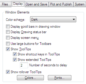
The Window Elements area
Color scheme
This controls either a dark or light color scheme for elements such as the status bar, title bar, ribbon bar, and the menu browser frame.
Display Scroll Bars in Drawing Window
Do you want Scroll bars at the bottom and side of your drawing area? Not me – leave it off.
Display Drawing Status Bar
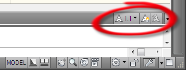
Displays the drawing status bar, which displays several tools for scaling annotations.
When the drawing status bar is turned on it displays at the bottom of the drawing area. When the drawing status bar is turned off, the tools found on the drawing status bar are moved to the application status bar. It puts it at the bottom of your drawing area.
Display Screen Menu
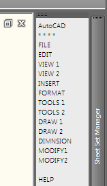
Displays the screen menu on the right side of the drawing area. The screen menu font is controlled by the Windows system font settings. If you use the screen menu, you should set the Windows system font setting to a font and font size that fits the screen menu size restrictions.
Talk about old school – here it is – you can get back that screen menu that you loved back in ACAD14. Boy does this bring back memories… I love it – but would never use it.
Use Large Buttons for Toolbars
Displays buttons in a larger format at 32 by 32 pixels. The default display size is 16 by 16 pixels.
Show Tooltips
Displays tooltips when you move the cursor over buttons on the ribbon, menu browser, toolbar, dialog Sheet Set Manager, and External References Palette.
Show shortcut keys in Tooltips
Displays shortcut keys in the tooltip (Alt + Key) (Ctrl + Key). I suggest leaving these as they are unless the tool tips annoy you.
Show extended Tooltips
Controls the display of extended tooltips.
Number of seconds to delay
Sets the delay time between the display of basic tooltips and extended tooltips. You an edit this to maybe 5 seconds to get them to not come up so often.
Show rollover Tooltips
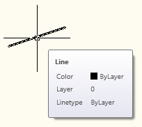
Controls the display of rollover tooltips for highlighted objects. So when you “roll over” an entity in ACAD – it shows you info about the object. The ROLLOVERTIPS system variable controls rollover tooltip display.
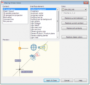
Colors
Displays the Color Options dialog box. Use this dialog box to specify colors of elements in the main application window. There are so many things you can change – but why bother, unless you cannot see them.
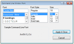
Fonts
Displays the Command Line Window Font dialog box. Use this dialog box to specify the font for the command window text. Go ahead – get creative 🙂 although the font choices are limited.
In general – leave all of these as they are.
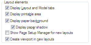
This area controls options for existing and new layout tabs. A layout is a paper space display of model space entities in which you can set up drawings for plotting.
Display Layout and Model Tabs
Displays the layout and Model tabs at the bottom of the drawing area. When this option is cleared, the tabs are replaced by buttons on the status bar.
Display Printable Area
Displays printable area in a layout. The printable area is represented by a dashed line and is determined by the selected output device. Objects drawn outside of the printable area are clipped or omitted when the drawing is plotted. Leave this on…
Display Paper Background
Displays a representation of the specified paper size in a layout. The paper size and plot scale determine the size of the paper background. Paper Space would not be the same without this.
Display Paper Shadow
Displays shadow around the paper background in layout. Makes it look so real 🙂
Show Page Setup Manager for New Layouts
Displays the Page Setup Manager the first time you click a layout tab. Use this dialog box to set options related to paper and plot settings. This is the only one that I might suggest you test out. If it is turned off, then your new layout tabs will just show up without asking for input.
Create Viewport in New Layouts
Creates a single viewport automatically when you create a new layout. If you do not want a default viewport cut, then turn this off.
Before we delve into the Display Resolution area…
Let’s discuss the following icons…
Notice at the top of the dialog box – this means that the variable that is flagged with this symbol next to it is stored in the drawing file only. All others are stored in the registry and apply to all drawings.
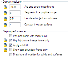
Display Resolution area
This controls the quality of the display of objects in your drawing. Be careful not to set these too high – it will impact performance.
Arc and Circle Smoothness
Controls the smoothness of circles, arcs, and ellipses. A higher number produces smoother objects, but more time is required to regenerate, pan, and zoom the objects.
Segments in a Polyline Curve
Sets the number of line segments to be generated for each polyline curve. The higher the number, the greater the performance impact. Set this option to a low value such as 4 to optimize performance for drawing.
Rendered Object Smoothness
Controls the smoothness of shaded and rendered curved solids. The value you enter for Rendered Object Smoothness is multiplied by the value you enter for Arc and Circle Smoothness to determine how to display solid objects.
Contour Lines per Surface
Sets the number of contour lines per surface on objects. A higher number decreases display performance and increases rendering time. The valid range is 0 to 2047. The default setting is 4. This setting is saved in the drawing.
Display Performance area
Controls display settings that affect performance.
Pan and Zoom with Raster and OLE
Controls the display of raster images and OLE objects when you use Realtime PAN and ZOOM. Leave this unchecked for best performance.
Highlight Raster Image Frame Only
Controls the display of raster images during selection. If this option is selected, only the frame of the raster image is highlighted when selected. Leave this unchecked that way images will display when selected.
Apply Solid Fill
Displays solid fills in objects. You must regenerate the drawing for this setting to take effect. Leave this checked.
Show Text Boundary Frame Only
Displays the frames for text objects instead of displaying the text objects. After you select or clear this option, you must use REGEN to update the display. I have turned this on from time to time, but usually leave it turned off.
Draw True Silhouettes for Solids and Surfaces
Controls whether silhouette edges of 3D solid objects are displayed when the current visual style is set to 2D Wireframe or 3D Wireframe. This option also controls whether mesh is drawn or suppressed when a 3D solid object is hidden. I leave this turned off since I do not do too many mesh objects.
Finishing up on the Display Tab…
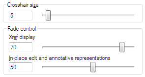
Crosshair size
Sets the size (percentage) of screen real estate that is taken up by the crosshairs.
Xref Display
Specifies the fading intensity value of externally referenced drawings. 70 is 70% of full display.
This option only affects the display on the screen. It does not affect plotting or plot preview.
In-place Edit and Annotative Representations
Specifies the fading intensity value for objects during in-place reference editing. Objects that are not being edited are displayed at a lesser intensity. (XFADECTL system variable)
You can modify external references and redefine block definitions from within the current drawing by using in-place reference editing. Both blocks and xrefs are considered references.
By editing the reference in place, you can modify the reference with the drawing displayed behind it – faded out.
Closing out the Files Tab…
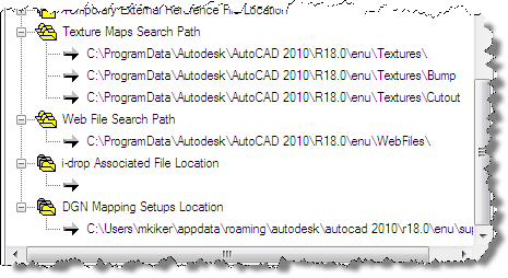
Texture Maps Search Path
You can add materials to objects in your drawings to provide a realistic look.
The use of mapping adds complexity and texture realism to the material. For example, you can replicate grass or brick patters or tile on a floor.
This setting specifies the folders to search for rendering texture maps.
Web File Search Path
Specifies the folders to search for photometric web files. No need to edit this.
i-drop Associated File Location
Specifies the location of data files associated with i-drop content. When the location is not specified, the location of the current drawing file is used.
DGN Mapping Setups Location
You can manage translation mapping setups for DGN file import and export operations.
You can create, modify, rename, or delete mapping translations based on your company’s CAD standards such as:
Change DGN level names to selected DWG layer names
Remap unsupported DGN linestyles to DWG linetypes
Remap lineweights and adjust color mapping
This specifies the location of the dgnsetups.ini file where DGN mapping setups are stored. This location must exist and have read/write permissions for DGN commands to function normally. Just leave this as is but make a note of where this is so you can refer to it later if needed.


