Layers in Underlay Files
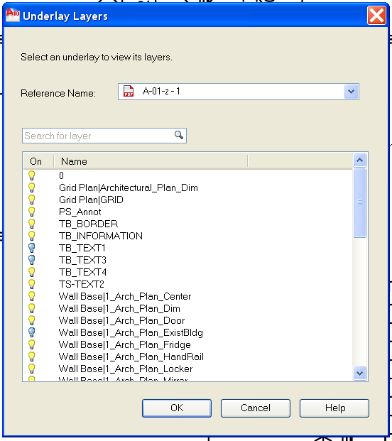
If the underlay file contains layers, you can control how the layers display after attaching the file. If the file does not contain layer information, the Underlay Layers dialog box does not display any layer information. Access this by right clicking after you have selected the Underlay.
Once you have selected the PDF Layers command you will get another dialog box allowing you to set layer visability
On February 2, 2010 my blog passed the 1,000,000 hits threshold.
I am always impressed that people read my blog. I have posted over 700 times (this is #706) and there are a lot more to come.
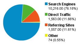
Here are some stats at the time of this posting.
Total Hits – 1,002,647
Average monthly hits – 16,172
First post – Dec. 14, 2004
Passed 600,000 hits – May 26th, 2008
Highest Pageview day – 4836 visitors on April 29, 2008 – a post of mine was included in the Bentley Newsletter – How to keep your job
Most hits on a single blog post – AutoCAD Keyboard Shortcuts – 20,864 hits
Highest referring site – caddigest.com
Browser/OS Stats
1. Internet Explorer / Windows 63.50%
2. Firefox / Windows 27.03%
3. Chrome / Windows 3.15%
4. Opera / Windows 1.95%
5. Safari / Macintosh 1.61%
6. Firefox / Macintosh 0.93%
7. Firefox / Linux 0.53%
8. Safari / Windows 0.42%
9. Mozilla / Linux 0.18%
10. Safari / iPhone 0.14%
Akismet stats – 34,211 spams caught, 592 legitimate comments, and an overall accuracy rate of 99.885%.
Recent hits came from:
Thank you to all my readers. It is gratifying to me to see you embrace my efforts.
When you have attached a PDF Underlay you can access it again in many ways.
You can underlay the following file types:
DWF – A DWF (Design Web Format) file is a highly compressed file format that is created from a DWG file.
DWFx – DWFx, the future of DWF, is based on the XML Paper Specification (XPS) format from Microsoft.
PDF – Adobe System’s document exchange format.
DGN – Bentley System’s Microstation format. DGN support is limited to V7/V8 DGN files and 2D objects. The 2D objects are imported or attached with full (X, Y, Z) coordinate information, as was present in the original file. If the file contains 3D solids, surfaces, or other 3D objects, a warning is displayed. This content is not supported in this file.
So if you do use Underlay – what options are there?
Snap to it.
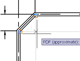
First off – OSNAPS work. You can snap to graphic elements in an Underlay. You cannot however use the Measure command. You can dimension from point to point though
Attaching an Underlay Multiple Times
You can reattach an underlay multiple times, treating them as a block. Each underlay has its own clip boundary and settings for contrast, fade, and monochrome.
Warning: You cannot bind an underlay to a drawing and you cannot edit or modify the underlay’s content.
Underlay Files in Xrefs
DWG file references (xrefs), in a drawing can include an underlay. In this situation, objects in the underlay are visible in the parent DWG file.
For example, drawing A includes a DWF underlay showing some mechanical details. You need the content of drawing A attached to your current drawing, drawing B. If you attach drawing A as an external reference to drawing B, the DWF underlay that was already attached to drawing A is also be present.
All of the property settings made to the underlay in the external reference, such as clipping boundaries, appear as they do in the parent drawing.
Password Protected Underlay Files
If a file you want to attach as an underlay is password protected, you are prompted to enter the password after you have selected the file. You cannot attach the file until you have correctly entered the password.
After an underlay is attached to a DWG file, you are prompted for the underlay file’s password each time you open the DWG file. If the DWG file is also password protected, or has several other protected drawing references attached, you may be prompted for multiple passwords.
This can get annoying…
If you change the path of an underlay to a file that requires a password, you are prompted for a password as well.
more annoying…
Note: DWF, DWFx, and PDF file passwords are case sensitive but DWG file passwords are not. To make synchronization between DWG and DWF file passwords easier, make sure the DWF, DWFx, and PDF file passwords match the DWG file password and are entirely uppercase.
Or better yet – don’t use passwords.
You can attach a DWF, DWFx, DGN, or PDF file as an underlay to a drawing file.
You reference and place underlay files in drawing files the same as you do raster image files so they are not actually part of the drawing file. Like raster files, the underlay is linked to the drawing file through a path name. The path to the file can be changed or removed at any time. By attaching underlays this way, you can use files in your drawing without greatly increasing the drawing file size. You can only view DWF and PDF underlays in the 2D Wireframe visual style. DGN underlays can be viewed in any visual style.
Note: Although underlay files are reproductions of their source drawing, they are not as precise as drawing files. Underlays may show slight discrepancies in precision.
You can use OSnaps with Underlay files.
If you have created or received a PDF file to use in CAD, you can attach it to your DWG file – here is how…
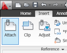
1. Open the Attach dialog box by going to the Insert Tab
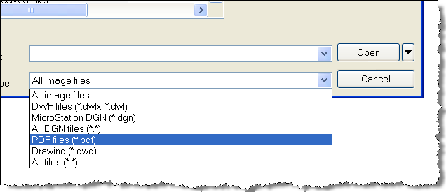
2. Select the file you want to attach by first changing the file type
Then select the file you want and hit Open.
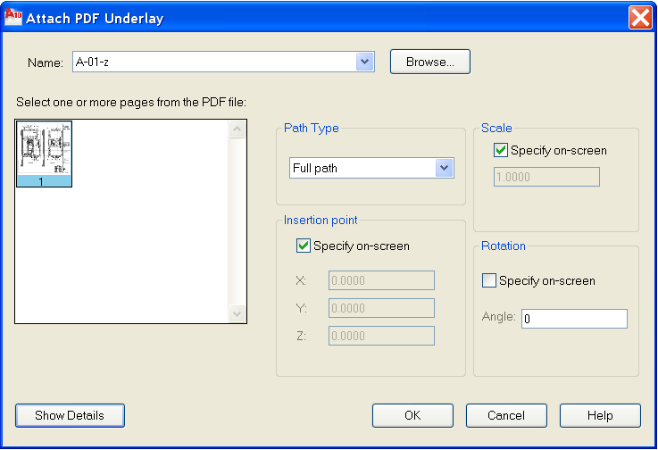
3. It will then open the standard attach file dialog box. You can select options as you choose.
It comes in as a PDF Underlay.
Generating PDF files to share information with others is a great way to get them design data without sending your CAD files.
Here is the process that is included with AutoCAD 2010.
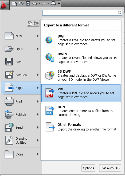
1. Select Export to PDF under the Big Red “A”
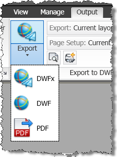
or you can select it fro the Output Tab onthe ribbon
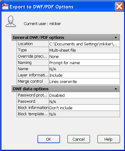
2.A dialog box opens and you can hit Save or select Options button
3. Several Options are presented. First by showing you the standards. You can add a password, overwrite precision,etc.
4. If you want to change an Option, just click on the option and a drop down will appear. No dropdown? then it cannot be changed.
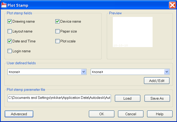
5. You can add a plot stamp if you like also. Some of the presets available are shown below. Check the ones you want to add. This is the exact same dialog box as plot stamping in the Plot command.
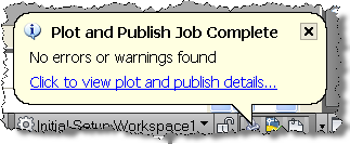
6. When you are happy that the PDF is all set to go – hit the Save button. When the file is created you will get a notification balloon in the lower right corner.
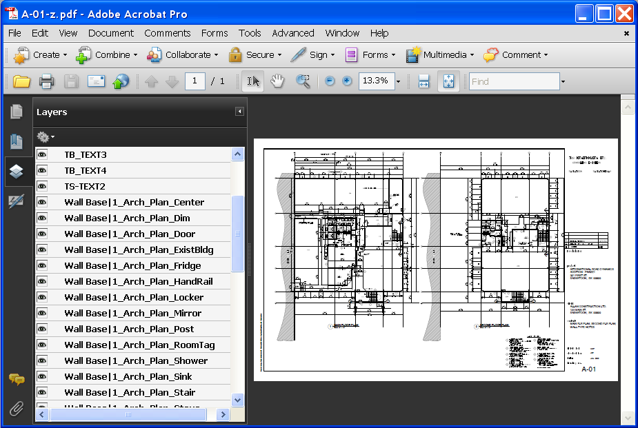
7. When you are done and you open the PDF you should see your completed PDF file with any data that you included.
Notes fromthe Help file:
Although transparent objects and wipeouts are displayed correctly in the PDF viewer, they may not print with the same visual fidelity when default print settings are used. If your drawing contains transparent objects, you may need to adjust some settings in Adobe Acrobat. Set Transparency Flattening to “Print as Image” or reduce the Raster/Vector Balance in Adobe Acrobat.
I have seen this happen – so be aware…
Simplified Upgrade Pricing Begins March 16, 2010
You need to be aware of a change that is coming…
From the Autodesk website…
Autodesk is introducing a new, streamlined upgrade pricing model on March 16, 2010. Under our current upgrade pricing model, the price of your upgrade depends on which product release you own. After March 15, 2010, your upgrade from any of the three previous software releases will cost 50 percent of the price of a new license, no matter which release you own.
From the Autodesk FAQ
1. What is Autodesk simplified upgrade pricing?
After March 16, 2010, Autodesk will introduce a new, streamlined upgrade pricing model that changes how Autodesk prices upgrades, cross-grades, and retroactive Subscription fees.2. How is Autodesk simplified upgrade pricing different from the way Autodesk sells upgrades and cross-grades today?
Today, upgrade and cross-grade prices and retroactive Subscription fees vary depending on which software release you are upgrading from. After March 16, 2010, upgrade and cross-grade prices and retroactive Subscription fees from the three previous software releases will be priced at 50 percent of a full license, no matter which release you are using today.3. When will simplified upgrade pricing take effect?
The last day to upgrade from Autodesk® 2007, 2008, and 2009 products with the current pricing model is March 15, 2010. The new simplified upgrade pricing model will go into effect after March 16, 2010.4. Why is Autodesk making this change?
We are streamlining our upgrade pricing based on feedback from customers and resellers that the current pricing model is too complex and no longer meets the needs of most of our customers.
More and more of our customers are choosing Autodesk Subscription as the most convenient and cost-effective way to keep their Autodesk software up-to-date. Customers tell us they prefer the budget and upgrade predictability of Autodesk Subscription. They also cite other advantages over traditional upgrades:
- The option to continue running previous versions of your software so there’s no interruption to your project flow
- Hassle-free and flexible licensing so you can use your Autodesk software in the office or at home (on selected products)
- Web support from Autodesk technical experts
- Self-paced training to help extend your Autodesk software skills
- Incremental product enhancements (on selected products) to increase your functionality between upgrades
For customers without Autodesk Subscription, simple, streamlined upgrade pricing should help make it easier for you to plan and budget your software upgrades. You will pay the same price—50 percent of a full license—to upgrade to the current release from any of the three previous versions, which means you can move when you’re ready.
Read more about it on the links above – there is a lot of info to review. Then you will know if it is better for you to tap into subscription before this kicks in or after.
If you are thinking of getting on subscription… time to think hard.
There are two types of archives that I suggest you do.
The first is Archiving Submittals. The second is Archiving Milestones.
This post is about archiving Project Submittals. Those contractual deliverables that come at specific times in the life of your project.
Archiving a project is critical to the retention of data for future use. Archiving CAD files when a submittal is completed will retain needed data.
The active project CAD files always remain in the proper folders as the project progresses from SD to Final Submittal. Never move the main files. They stay in the same folder that they are created in. Some firms may move files from one folder to another as the project progresses. I do not recommend that practice. Users can get confused on which file is the latest. Just keep them in the same folder.
Once the files & folders have been created and files generated, the CAD files do not move. They are not moved to new folders when there is a change in project phase, such as, SD, DD, CD or As-built.
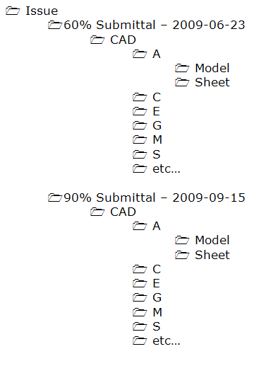
When you move from one phase of a project to the next you may archive a copy of the complete issued files and folders under a new folder called “Issue”.
Copy the complete folder tree into the Issues folder as a submittal is made. This means that under the Issue folder there will be many subfolders. Only files needed to reproduce the Issue should be copied. Do not copy non-issued files.
The “live” CAD files remain in the proper folders and continue to be developed. When another milestone is reached another archive will be created under the Issue folder.
Burning CDs or DVD can be done once the Issues is complete. Issues that are no longer needed can be removed from the server after they are burned to DVD.
Archiving Issues and Submittals should be done as outlined in a previous post.
As projects progress, there may be a need to save prior versions. Milestones are reached in the design that are not at a submittal point. Changes in the design cause major reworking of files. Saving the older versions can come in handy if the client or the designer needs to step back to a prior version. There also may be a need to archive unused non-issued project-wide data.
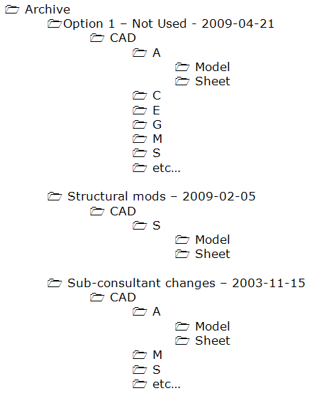
When this is needed, it should be done in an “Archive” folder.
The folder will be broken down similar to the Issue folder.
No official Issue data goes into the Archive folder. Project archives are for snapshots of the project at internal milestones. If a major design change will take place, you may want to archive the old data before it is modified.
The purpose of this data is so that you can refer to it or regain some files if needed later.
The “live” CAD files remain in the proper folders and continue to be developed. When another milestone is reached another archive may be created under the Archive folder.
When plotting to hardcopy you see the results of your efforts instantly. You get a visual product that can quickly be scanned visually.
Finding error on hardcopy is often easier than finding them on digital copies.
Do you have a method for reviewing the output that is created digitally before it is sent to others?
Here are some items that can be standardized for the main output types.
PLT Files (does anyone still create these?)
Generating, storing and delivering PLT files is determined on a project by project basis.
When used they should be generated Full size. The PLT File name must reflect the Sheet File name.
PDF Files
PDF files are encouraged for distribution of data for plotting and review only. AutoCAD now allows for PDF backgrounds and this may be used also.
When used, PDF’s should be generated Full size. The PDF File name must reflect the Sheet File name.
DWF files
DWF files can be created also. The DWF Filename must reflect the Sheet File name. Design Review is now free – so creating and using DWF files is getting easier every day.

