More on Plotting and Publishing

Plot and publish log file – turn it off – you most likely will never need this.
If you did create a log it would include:
- Job ID
- Job name
- Sheet set name
- Category name
- Date and time started and completed
- Sheet name
- Full file path
- Selected layout name
- Page setup name
- Named page setup path
- Device name
- Paper size name
- Final status
If you do create a file – it will be located in the location set on the Files tab of the Dialog box.
You can save one big giant file that is appended to as you create new plots – or check the other box and get one file per process job. (Not one per file, but one per job)
It creates a CSV file that can be opened in Excel.
Here is an example (not in Excel)


Closing out the left side of this dialog box brings us to Auto Publishing…
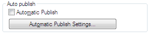
Checking the Automatic Publish radio button will publish DWF or DWFx or PDF files upon your selected action. So you can set AutoCAD to create DWF or PDF files when you save or close a file.
This may be overkill for most of you. Creating a DWF or PDF every time you close a file may be overdone.
When you select the Setting button you get the following:

This dialog box contains the following options:
Auto-Publish Options
Specifies where DWF or PDF files are saved when you publish drawing sheets.
Publish on – Specifies when the publishing takes place. You have several options here.
Save (Publishes when the drawing is saved)
Close (Publishes when the drawing is closed)
Prompt on Save (Prompt when the drawing is saved)
Prompt on Close (Prompt when the drawing is closed)
If you select the Prompt you get a dialog popup like this:

Location – Specifies a directory where exported files are saved when you publish drawings by selecting the following options in the list. This is not set in the Files Tab of Options.
Click the […] button to specify a new location to save the published drawings.
Include – Specifies whether to publish the model, the layouts or both the model and layouts when you publish drawings.
General DWF/PDF options
Specifies options for creating a single-sheet or multi-sheet DWF, DWFx, and PDF files.
File Format – Specifies whether the DWG should be published as a DWF, DWFx, or PDF file.
What is DWFx? DWFX is an Autodesk DWF XPS Document. Autodesk has teamed with Microsoft to seamlessly integrate DWF technology with Windows Vista using the XML Paper Specification (XPS). DWFx files can be opened directly within Microsoft`s XPS Viewer, which is automatically installed with Microsoft Vista, bundled with .NET 3.0, and is available as an optional download for Windows XP users.
Type – Specifies that a single-sheet or a multi-sheet is generated for all the sheets listed in the Publish dialog box.
Layer Information – Specifies whether layer information is included in the published DWF, DWFx, or PDF file.
Note: Layer information for 3D DWF entries does not get published.
Merge Control – Specifies whether overlapping lines overwrite (the top line hides the bottom line) or merge (the colors of the lines blend together).
DWF Data Options
Lists and allows you to specify the data that you can optionally include in the published file.
Password Protection
Specifies options for protecting DWF, DWFx, or PDF files with passwords.
Block Information
Specifies whether block property and attribute information is included in the published DWF, DWFx, or PDF files.
Block Template File
Allows you to create a new block template (DXE) file, edit an existing block template file, or use the settings of a previously created block template file. This only becomes available when you set Block Info to Include.
I had the pleasure to attend COFES 2010. This event is always an opportunity to glimpse into the future.
I have attended before and the event is going strong. Well attended by industry representatives, software developers and User Group reps. It is a grand collection of those who influence the software and industries that your are involved in.
Highlights of this year included HP and Intel discussing the next generation of chips and hardware that will make your services run faster. Is it time to move to a new platform? Do you need to move from a PC to a workstation? Are you on the right hardware?
Intel mentioned the Tick-Tock process of development where:
Year 1: First the “Tick”
Intel delivers new silicon process technology, dramatically increasing transistor density while enhancing performance and energy efficiency within a smaller, more refined version of our existing microarchitecture.
Year 2: Then the “Tock”
Intel delivers entirely new processor microarchitecture to optimize the value of the increased number of transistors and technology updates now available.
HP discussed SkyRoom – which I want to check out.
Other items that are getting traction:
The Chaos Report for IT – failures of projects
Closing out the Open Tab…

Demand loading continues with ObjectARX Application info:

Here is the definitions from the AutoCAD Help files:
- Disable Load on Demand: Turns off demand-loading.
- Custom Object Detect: Demand-loads the source application when you open a drawing that contains custom objects. This setting does not demand-load the application when you invoke one of the application’s commands.
- Command Invoke: Demand-loads the source application when you invoke one of the application’s commands. This setting does not demand-load the application when you open a drawing that contains custom objects.
- Object Detect and Command Invoke: Demand-loads the source application when you open a drawing that contains custom objects or when you invoke one of the application’s commands.
I suggest you set it to the last one on the list.
Proxy image display is also controlled here.

A proxy is created when you open a drawing containing custom objects created by an application that you may not have. A proxy is also created when you issue a command that unloads a custom object’s parent application.
Turn on these settings as shown above and set the dialog box to display.
Next on the Open and Save Tab we have the External XRef options. Xrefs are external files that are Attached or Overlaid to show information from other drawings. They load and refresh every time you open the host drawing.

Demand Loading Xrefs defines how you want your system to handle XRefs. There are three options:
Disable; Enable and Enable with Copy.

When you set it to Disable then Demand Loading is turned off and the entire drawing is loaded (this takes longer).
When you set it to Enable, it turns on Demand loading. This improves performance by only opening areas that you need. If something is clipped, it is not loaded. If there is layer indexing, it only loads what you need. Enabled though allows the XRef to be locked and others cannot edit the file while you have it referenced.
When you set it to Enable with Copy, a temporary copy of each referenced drawing file is stored in the folder set in the Options dialog box under the Files Tab. Additionally, xrefs load faster when you work across a network: the performance enhancement is most pronounced when you open drawings with many xrefs.
Set it to Enable with Copy.
Retain changes to Xref Layers is the grand old VISRETAIN variable. One that I think Autodesk needs to make some heavy upgrades on.
When this is turned on (checked) Xref-dependent layer changes made in the current drawing take precedence over the XRef original layer settings. Layer settings are saved with the current drawing’s layer table and persist from session to session. If you change the original file – the drawings that have this turned on and have edits to layer setting will never see the original changes.
Allow other users to Refedit current drawing controls whether the current drawing can be edited by others who have it referenced.
The Open and Save Tab continues with the File Open options. Here you can set the number of files to display under the File Menu pulldown. I crank this up as high as it will go. Nine is as high as it will go…
I also turn on “Display full path in title” check box. This will show you the full path above the drawing area so that you can see where your drawing is located.

The Applications Menu area defines how many Recent files to show when you are looking at the Open Dialog box in the History section. You can have up to 50 listed. I tried 300, but it would not stick 🙂
The next part of the Open and Save Tab is the File Safety Precautions. This area helps you avoid data loss and detect errors.

Automatic Save
AutoCAD automatically saves your files depending upon the setting in this box.
Backup files help ensure the safety of your data. If a problem occurs, you can restore a drawing backup file. If a problem occurs, you can restore a drawing backup file.
In the Options dialog box, on the Open and Save tab, you can specify that backup files are created when you save drawings. If you do, each time you save a drawing, the previous version of your drawing is saved to a file with the same name and a .bak file extension. The backup file is located in the same folder as the drawing file.
You can revert to your backup version by renaming the .bak file to a file with a .dwg extension. You may want to copy it to a different folder to avoid overwriting your original file. You can rename it – open it – verify that it is what you want and then overwrite the old file.
If you turn the automatic save option on, your drawing is saved at specified time intervals. By default, files saved automatically are temporarily assigned the name filename_a_b_nnnn.sv$. They will be located in the folder you set in the Options Dialog box under the Files Tab.
Here is how the file name is built by AutoCAD:
“Filename” is the current drawing name.
“a” is the number of open instances of the same drawing file in the same work session.
“b” is the number of open instances of the same drawing in different work sessions.
“nnnn” is a randomly generated number.
These temporary files are automatically deleted when a drawing closes normally. In the event of a program failure or a power failure, these files are not deleted. You may have to go into the folder and delete the leftover files from time to time.
To recover a previous version of your drawing from the automatically saved file, rename the file using a .dwg extension in place of the .sv$ extension before you close the program. Otherwise the files may no longer be there.
Getting back your autosave is one way of restoring data, but what happens if the system crashes?
Recovering from a Crash
A hardware problem, power failure, or software problem can cause AutoCAD to terminate unexpectedly. If this happens, you can restore the drawing files that were open.
After a program or system failure, the Drawing Recovery Manager opens the next time you start AutoCAD. Drawing Recovery Manager displays a list of all drawing files that were open, including the following drawing file types:
Drawing files (DWG)
Drawing template files (DWT)
Drawing Standards files (DWS)
Note: Unsaved drawings that are open at the time of an unexpected failure are not tracked by the Drawing Recovery Manager. Be sure to save your work after you begin, and regularly thereafter.
For each drawing, you can open and choose from the following files if they exist:
DrawingFileName_recover.dwg
DrawingFileName_a_b_nnnn.sv$
DrawingFileName.dwg
DrawingFileName.bak
Note: The drawing, backup, and recover files are listed in the order of their time stamps—the time when they were last saved.
If you close the Drawing Recovery window before resolving all affected drawings, you can open Drawing Recovery at a later time with the DRAWINGRECOVERY command.
The rest of the settings on this page are not as useful as they use to be. Leave them set as they are. Do not turn on the logfile. It grows too large too quick.
Security Options will allow you to set a password or attach a digital signature to a file.
The first area on this tab is the File Save settings.

Save As
Displays the file formats that can be used when saving a file with SAVE, SAVEAS, QSAVE, and WBLOCK. Whatever you set here will be used as the default setting for all drawings that are saved when you use SAVE, SAVEAS, QSAVE, and WBLOCK.
Note: AUtodesk does not change the file formats with each release. They generally go three releases before updating the file format. So AutoCAD 2004 is the drawing file format used by the AutoCAD 2004, 2005, and 2006 releases. AutoCAD 2007 is the file format used by AutoCAD 2007, 2008, and 2009 releases. You get the idea. You can also set it to DXF – if you wanted to. DWT is a format for Template files.

Visual Fidelity for Annotative Objects
When working with annotative objects, this option allows you to maintain visual fidelity for these objects when they are viewed in AutoCAD 2007 format and earlier releases. Visual fidelity is controlled by the SAVEFIDELITY system variable.
If you work primarily in model space, it is recommended that you turn off visual fidelity (set SAVEFIDELITY to 0). However, if you need to exchange drawings with other users, and layout fidelity is most important, then visual fidelity should be turned on (set SAVEFIDELITY to 1).
![]() It is a good time to bring up the little “i” in the circle. It is called the Information Icon. Hit this and go instantly to the help files for the setting identified with this symbol.
It is a good time to bring up the little “i” in the circle. It is called the Information Icon. Hit this and go instantly to the help files for the setting identified with this symbol.
Maintain Drawing Size Compatibility
Specifies whether or not the AutoCAD 2009 and earlier object size limits are used instead of those for AutoCAD 2010. Click the information icon to learn more about object size limits and how they affect opening and saving a drawing. (LARGEOBJECTSUPPORT system variable)
Drawings saved to a legacy drawing file format (AutoCAD 2007 or earlier) do not support individual objects greater than 256MB. With the AutoCAD 2010 drawing file format, these limitations have been removed allowing you to save objects that are greater in size. You will not be impacted by this very often.
When saving to a legacy drawing file format (AutoCAD 2007 or earlier), the drawing cannot contain large objects; there might be compatibility issues with trying to open the drawing. The LARGEOBJECTSUPPORT system variable controls the large object size limits used and the warning messages displayed when a drawing is saved.
The following explains how object size limits for drawings is determined:
Drawing files cannot exceed an internal size limit of 4GB. This size is based on the total size of all objects in a drawing when uncompressed. Since a drawing file is normally compressed, the final size of a saved drawing file on disk will vary based on the size and number of objects in a drawing.
Each individual object in a drawing cannot exceed an uncompressed size limit of 256MB. For example, a mesh object, when saved to a file and compressed, might be 75MB in size while the same object when uncompressed might be 257MB.
In these situations, the drawing cannot be saved to an AutoCAD 2007 or earlier file format until the issues are resolved. You can resolve the size limits by breaking the drawing or objects up into several drawings or objects.
Note: When working with the 64-bit release of AutoCAD, you can work more efficiently with large objects and drawings. However, the drawing files you create might be too large to open with the 32-bit release of AutoCAD. This might bite you in a mixed environment.
Thumbnail Preview Settings

This dialog box allows you to set Home Views so that you always get the same look. Default is to show you the last saved viewing area. You can also set Sheet Set Manager thumbnails and Named View thumbnails.
Incremental Save Percentage
Sets the percentage of potentially wasted space in a drawing file. Full saves eliminate wasted space by resorting and compressing file information. Incremental saves are faster but they increase the size of your drawing. If you set Incremental Save Percentage to 0, every save is a full save. For optimum performance, set the value to 50. If hard disk space becomes an issue, set the value to 25. If you set the value to 20 or less, performance of the SAVE and SAVEAS commands slows significantly. (ISAVEPERCENT system variable). If you are in and out of drawings all day then you will be doing Full saves all the time. If you spend a lot of time in the same file, then your quick saves “QS” will be faster but take up more space -this is usually not an issue for most users. Leave it set to 50.
We now move to the third tab on the Option Dialog box. It is the Open and Save Tab.

When working in AutoCAD you are constantly opening or saving files. The little gems that reside in this dialog box can save you time and frustration. You would be surprised at how much trouble you can get into with simple commands like Open and Save (Saveas). So many settings go into the initial creation of files. Some we covered in the Files Tab and you should go back and read those.
NOTE: Notice right above the Open and Save Tab there is a listing of the Current Profile: If you are using profiles, the name will be displayed in the Options Dialog. Mine is showing the Initial Setup Profile as I have not changed it yet. We will discuss Profiles when we get to that tab on the Options Dialog.
