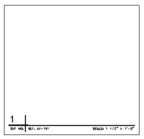
Standard Detail Module
I suggest that you create a standard box or module that contains the details. This provides modularity and you can drop in a detail to a standard area on your files.
The standard drawing module size shall be X inches high by Y inches wide bounding box. The size you use is defined by dividing up the available drawing area of your border into a grid system. The bounding box for one grid becomes your size.
Details that require a greater area may be created by using multiple bounding boxes. A ¼” “Safe Zone” buffer should be used to insure that detail entities do not contact the bounding box.
The details shall be created with the insertion base point set at the lower left or right corner of the detail boundary. This will be the snap and drag point if they are inserted as blocks.
Details shall be drawn in Full Scale in Model Space. Annotation in details shall be created to reflect the desired plotted scales.
The Detail Title shall be included with the detail. All other titling information will be placed in the sheet file (like detail numbers)
Do not add the scale text (1/2″ = 1′-0″) to the detail if you change the scale often when using the detail. This should be done in the sheet file when the detail is placed. Otherwise add the scale to the detail.
The illustration of material textures in the details should be done by using the standard hatch patterns provided. Under no circumstances should hatching patterns be exploded.
