 |
|
|
A
change of name from "Newsletter" to "Journal" for my monthly
efforts. I will now refer to this publication as the
CADDManager.com named "Site of the Week" on TenLinks In This Journal - Table of Contents February brings many of you into the "bleak mid winter" of your year when you are digging out or digging in. The weather and its resulting problems have been a concern for many areas from Southern California to the Northeast, from Seattle to Florida. Freezing rain, mud slides, snowfall measured in "feet per hour". Tragic natural events in the Indian Ocean. You name it, we have seen it. I want to talk about another kind of "weather", actually the word I want to talk about is "whether". CAD Managers have to deal with "whether" all the time. Whether we upgrade now? Whether to move to Arch Desktop or Land Desktop or REVIT or Civil 3D? Whether to sign up for subscription or not? Whether to allow that rouge user to continue to rock the boat, or whether to face them head on? Whether to get out of bed each day and drag yourself to work? Many kinds of whether come in to your work life, not to mention the whether's of your home life. Decision making and progress are based on how well you handle these and other questions. Do I have an answer for these kinds of questions? I do for my environment, but it may not work in yours. Each of us need to work through these and other issues every day. Face them head on. Work them through by taking into account everything you have in your resources. Think about the impact on your firm, your users and your job. Then make a decision and move ahead.
Mark W. Kiker, Editor
Pareto Analysis - Selecting the Most Important Problem to Address ETransmit - Part 3 Tech Tip - ABS Export to AutoCAD Latest CAD News - link to our website Latest Web Update - CAD Leadership - Part 4 Take our latest Survey - Tell us about your office...
Pareto Analysis - Selecting the Most Important Problem to Address
Have you
heard of Pareto analysis? It is a very simple technique that
helps you to choose the most effective changes to make.
The method was invented by Vilfredo Pareto (1848-1923), an Italian economist and sociologist. He discovered that 80 percent of the wealth in Italy was held by only 20 percent of the population, hence the 80/20 rule. The idea that by doing 20% of work you can generate 80% of the advantage. Pareto analysis is a formal technique for finding the changes that will give the biggest benefits. It is useful where many possible courses of action are competing for your attention. You most likely do this all the time without realizing it. How to use tool: Let’s apply it to CAD Production troubles. To start using the rule, write out a list of the problems you have. If you have a long list, group it into related changes. Then score the items or groups. The scoring method you use depends on the sort of problem you are trying to solve. For example, if you are trying to improve profitability, you would score options on the basis of the profit each group might generate. If you are trying to improve user satisfaction, you might score on the basis of the number of complaints eliminated by each change. The first problem to tackle is the one that has the highest score. This one will give you the biggest benefit if you solve it. The options with the lowest scores will probably not even be worth bothering with - solving these problems may cost you more than the solutions are worth. Example: A CAD Manager has been assigned the task of deciding how to increase productivity. He starts his research to find out what users and managers complain about. He gets the following comments back from Users and Managers:
The CAD Manager groups these problems together, then scores each group by the number of complaints, and orders the list:
By doing the
Pareto analysis above, the manager can better see that the vast
majority of problems (77%) can be solved by improving staff
skills, correct and upgrade plotters, and upgrade the PC
platforms.
Pareto
Analysis is a simple technique that helps you identify the
most important problem to solve first.
Pareto analysis not only shows you the most important problem to solve, it also gives you a score showing how severe the problem is. Whether you get this formal or not, you still should use some form of this type of process to prioritize your efforts. Mark W. Kiker Back to In This Journal - Table of Contents
ETransmit - Part Three Last month we began to investigate ETransmit... let's continue...
Transmittal Options This opens the door to set your preferences and options for organizing the files and folders that are included in the transmittal package. Use Organized Folder Structure Sets up the folder structure for the transmittal from the files being transmitted. The root folder is the top-level folder within the folder tree. Keep in mind:
This option is not available if you're saving a transmittal package to an Internet location.
Source
Root Folder The source root folder also contains the sheet set data (DST) file when a sheet set is transmitted.
Browse
Place All
Files in One Folder
Keep Files
and Folders As Is - Check this one on
Include
Fonts – Check this one on
Send
E-mail with Transmittal
Set
Default Plotter to 'None' – Check this one on
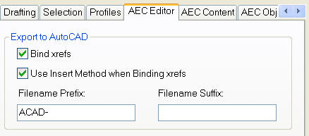
Bind
External References – AARGH – Please don’t use this
Prompt for
Password
Include
Drawing Set Data and Files
Transmittal Setup Description
File List 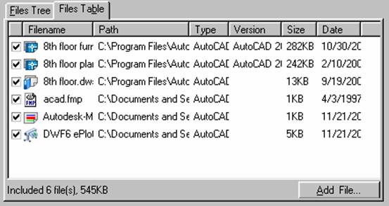 Next month... ETransmit Sheet Sets Back to In This Journal - Table of Contents
ScriptPro lets you automate some of the tedious commands you have to do across several files. You can set it up to purge and zoom extents. Using ScriptPro you can apply a set of command line executions to multiple drawings by simply specifying a script file and the list of drawings to process. Get it at http://www.autodesk.com/migrationtools under Autodesk Customization Conversion Tools Back to In This Journal - Table of Contents |
|||||||||||||||||||||||||||||||||||||||||||||||||||||||||||||||||||||
|
Not a current subscriber to the CADD Manager
Journal? Why not share the CADD Manager
Journal
with a friend? Received
this by mistake? |

|
CADD Manager Journal
is a publication of the Core Technology Group. |