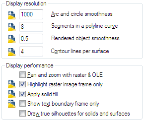
Before we delve into the Display Resolution area…
Let’s discuss the following icons…
Notice at the top of the dialog box – this means that the variable that is flagged with this symbol next to it is stored in the drawing file only. All others are stored in the registry and apply to all drawings.
Display Resolution area
This controls the quality of the display of objects in your drawing. Be careful not to set these too high – it will impact performance.
Arc and Circle Smoothness
Controls the smoothness of circles, arcs, and ellipses. A higher number produces smoother objects, but more time is required to regenerate, pan, and zoom the objects.
Segments in a Polyline Curve
Sets the number of line segments to be generated for each polyline curve. The higher the number, the greater the performance impact. Set this option to a low value such as 4 to optimize performance for drawing.
Rendered Object Smoothness
Controls the smoothness of shaded and rendered curved solids. The value you enter for Rendered Object Smoothness is multiplied by the value you enter for Arc and Circle Smoothness to determine how to display solid objects.
Contour Lines per Surface
Sets the number of contour lines per surface on objects. A higher number decreases display performance and increases rendering time. The valid range is 0 to 2047. The default setting is 4. This setting is saved in the drawing.
Display Performance area
Controls display settings that affect performance.
Pan and Zoom with Raster and OLE
Controls the display of raster images and OLE objects when you use Realtime PAN and ZOOM. Leave this unchecked for best performance.
Highlight Raster Image Frame Only
Controls the display of raster images during selection. If this option is selected, only the frame of the raster image is highlighted when selected. Leave this unchecked that way images will display when selected.
Apply Solid Fill
Displays solid fills in objects. You must regenerate the drawing for this setting to take effect. Leave this checked.
Show Text Boundary Frame Only
Displays the frames for text objects instead of displaying the text objects. After you select or clear this option, you must use REGEN to update the display. I have turned this on from time to time, but usually leave it turned off.
Draw True Silhouettes for Solids and Surfaces
Controls whether silhouette edges of 3D solid objects are displayed when the current visual style is set to 2D Wireframe or 3D Wireframe. This option also controls whether mesh is drawn or suppressed when a 3D solid object is hidden. I leave this turned off since I do not do too many mesh objects.
